How Do Flex PCBs Differ From Rigid-Flex PCBs?
Flex PCBs Differ From Rigid-Flex PCBs
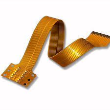
A flex PCB has the same electrical connections as any other printed circuit board but uses a flexible base material that allows it to bend and fold. This enables flex circuits to be used in more compact and innovative electronics. The ability to withstand vibration, dissipate heat and fold in different shapes makes this type of PCB ideal for mobile devices, medical equipment, wearables and more.
A PCB manufacturer will create a flex circuit by stacking a layer of conductive copper onto an overlay of polyimide. Typically, a flexible circuit will also include layers of insulating material. This is because the layer of insulating copper on the bottom of the flex circuit must be able to protect the conductive layers from damage and corrosion. Similarly, the layer of insulating material on the top must be able to keep out moisture and contaminants.
While this may seem like a simple process, the fact is that each layer of a flex circuit has different properties and requires its own manufacturing processes. As such, a flex pcbs is more complex and costly to produce than a rigid one. This is especially true if the design includes multiple flex sections.
How Do Flex PCBs Differ From Rigid-Flex PCBs?
To reduce costs, a flex PCB can be manufactured using the same materials as a rigid board. The conductive copper layer can be made from electro-deposited copper or, for cost savings, rolled annealed copper. In addition, the insulating layer can be made from a standard FR4 material or other types of insulating materials.
Another way to reduce the cost of a flex PCB is to use a layered construction with the flex layer as the bottom layer. This helps to simplify the fabrication and assembly processes. Additionally, the flex layer can be made thicker to accommodate components such as plated through holes (vias) or other features that require a high-reliability construction.
Depending on your design, you might choose to add what is called stiffeners to selected areas of the flex circuit. Stiffeners are areas of rigid material (usually FR4) added to a flex circuit in order to give it additional mechanical support. This is particularly important for areas of the flex circuit that contain SMT and PTH components to prevent the flex circuit from being bent at or near these components, which could compromise their integrity.
Flexible printed circuit boards (PCBs), often abbreviated as flex PCBs, represent a revolution in the realm of electronic engineering. These innovative components offer unparalleled versatility, enabling the creation of electronics that conform to unique shapes and designs previously unimaginable with traditional rigid PCBs. With their remarkable flexibility, durability, and lightweight nature, flex PCBs have become indispensable in numerous industries, from consumer electronics to aerospace and healthcare.
During the design phase, working with integrated MCAD and ECAD tools within a single application makes it much easier to define your flex PCB’s bending region and prepare it for manufacturing. This is because you have a clear view of your rigid-flex PCB’s layer stack and structure, while still being able to generate all of the necessary Gerber files and assembly drawings for manufacturing.